OSCILLATING BOUNDARY
HOW OSCILLATING BOUNDARY WORKS

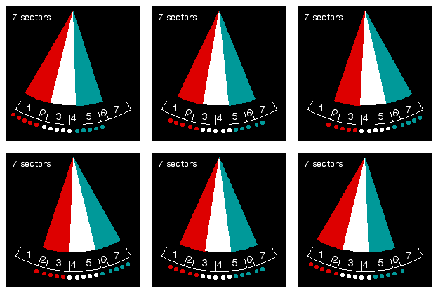
Sectors 1 and 7 can be partially or completely masked. Otherwise, all oscillating sectors must be the same size, and this may not be larger than 20% of the total subtense.
The size of each sector (1-7) depends on the total subtense of the light, the width of coloured filter glass, and the distance of oscillation. These are all calculated by Vega to give the required result.
The outer sectors (1 & 7) appear as a flashing or occulting light of one colour. This can be useful for helping a pilot to set up a difficult turning manoeuvre, by marking points on the approach to the turn.
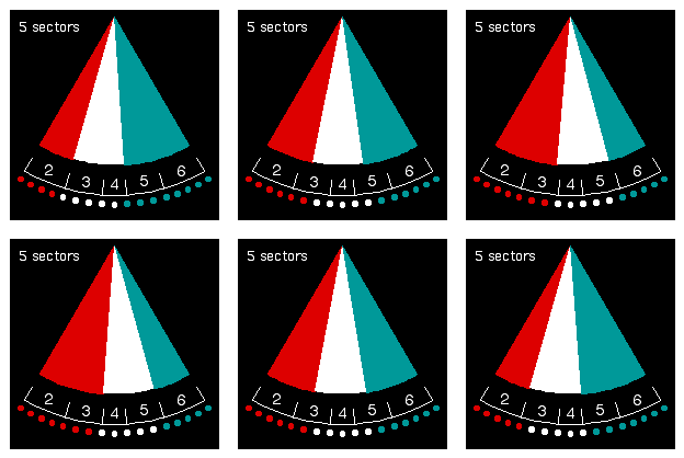
Where the intention is to keep a vessel accurately located on a desired track, the 5-sector configuration is normally used. (On slow connections please allow time for the graphic to load and start moving. The green sector looks blue on some monitors.)
TECHNIQUES FOR USE
Some pilots have developed their own techniques. On large vessels the pilot (or an assistant) may walk across the bridge to find the edge of the fixed white sector and then check the distance back to the centre of the vessel.
Knowing the distance to the light enables the distance from centreline to be determined. Any lateral movement is obvious within a few seconds. It may seem complicated when described in words and pictures, but in practice it is simple and intuitive to use.

USE OF OSCILLATING BOUNDARY IN NAVIGATION
For vessels attempting to stay very close to a centre line, the oscillating boundary gives immediate and accurate warning of a lateral deviation as small as 2 metres (6 feet) when at a distance of 6 kilometres (3 nautical miles) from the light. The warning comes as the fixed white light is interrupted by a brief flash of colour every 3 seconds. The duration of the flash increases as the vessel moves further from the centre line.
Additional Sectors without Additional Colours
It is not wise to use more than 3 colours in a signal light which relies on the correct identification of the colour for interpretation. The oscillating boundary can provide up to four additional sectors without using any more colours than red, white and green.
Proportional Indication of Lateral Movement
As the observer moves across an oscillating sector, the duration of one colour flash relative to the other changes continuously. As one colour increases, the other decreases, but one cycle is always 3 seconds.

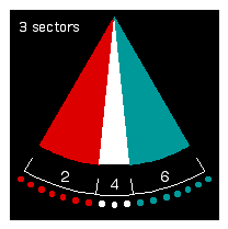
(Left) Without oscillating boundary there would be only three fixed sectors, hence a maximum of three sectors.
Also, there would be no "proportional signal", meaning no change with movement across the sector.

